• page_head_Bg

High-Range Deep Well Water Quality Monitoringntegrated 4G EC & Level Sensor

1. Executive Summary

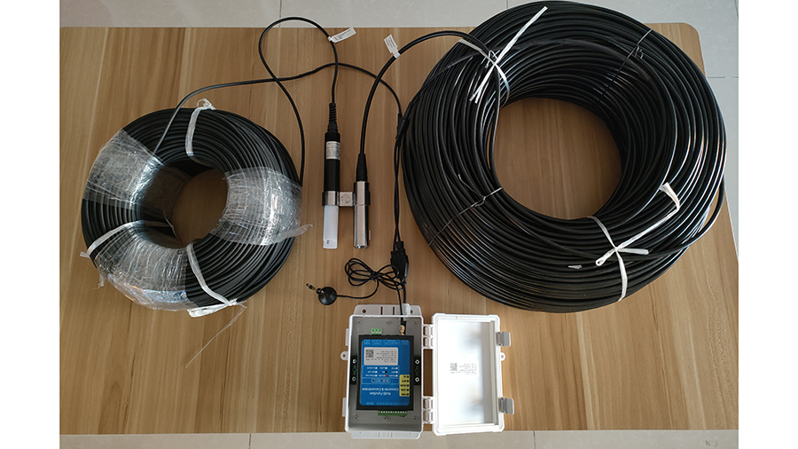
To monitor deep well water quality effectively, an integrated 4G sensing system like the RD-ETTSP-01 combined with a Pneumatic Water Gauge is the industry standard. This 5-parameter solution simultaneously measures Electrical Conductivity (EC), TDS, Salinity, Temperature, and Liquid Level. By utilizing a corrosion-resistant PTFE electrode and a 4G/LoRaWAN gateway, operators can transmit real-time data from 10m+ depths to cloud servers. This architectural approach ensures stable performance in acidic or high-salinity industrial environments where traditional pressure transducers and standard electrodes typically fail.

water level&ec for deep well

2. Why PTFE Electrodes Outperform in Acidic Industrial Waste

Based on our 15 years of manufacturing industrial IoT nodes, we have found that standard electrodes degrade rapidly in deep-well environments containing high mineral content or industrial runoff. The RD-ETTSP-01 solves this through a PTFE (Polytetrafluoroethylene) electrode design, providing unmatched resistance to acids, alkalis, and high-salinity solutions.
Architectural Insight: The physical integration of the EC probe and the Pneumatic Water Gauge into a shared mounting bracket allows for a compact footprint, essential for 4-inch or 6-inch well casings. Unlike traditional pressure transducers that can foul in silty wells, the Pneumatic Gauge uses gas-medium sensing to provide a 0.2% accuracy level without direct liquid contact with sensitive internal diaphragms. Note: The gauge is suitable for any gas or liquid that does not corrode stainless steel.

3. Technical Specifications & Impedance Data

The following data reflects the high-stability digital linearization correction integrated into our 2025 sensor series.
Parameter
Measurement Range
Accuracy
Resolution
EC (Conductivity)
0 ~ 2,000,000 µS/cm
±1% FS
10 µS/cm
TDS (Total Dissolved Solids)
0 ~ 100,000 ppm
±1% FS
10 ppm
Salinity
0 ~ 160 ppt
±1% FS
0.1 ppt
Temperature
0 ~ 60 °C
±0.5 °C
0.1 °C
Water Level (Pneumatic)
0 ~ 10 meters
0.2%
1 mm
Electrical Interface & Signal Requirements:
• Digital Output: RS485 (Standard Modbus-RTU, Address: 01).
• Analog Output: 4-20mA, 0-5V, or 0-10V (Note: Analog usually supports Salinity only).
• Supply Voltage: DC (for 4-20mA/0-10V).
• Pneumatic Gauge Power: 12-36VDC (24V Typical).
Maximum Impedance for 4-20mA Current Signals: | Supply Voltage | 9V | 12V | 20V | 24V | Max Impedance | 125Ω | 250Ω | 500Ω | >500Ω |

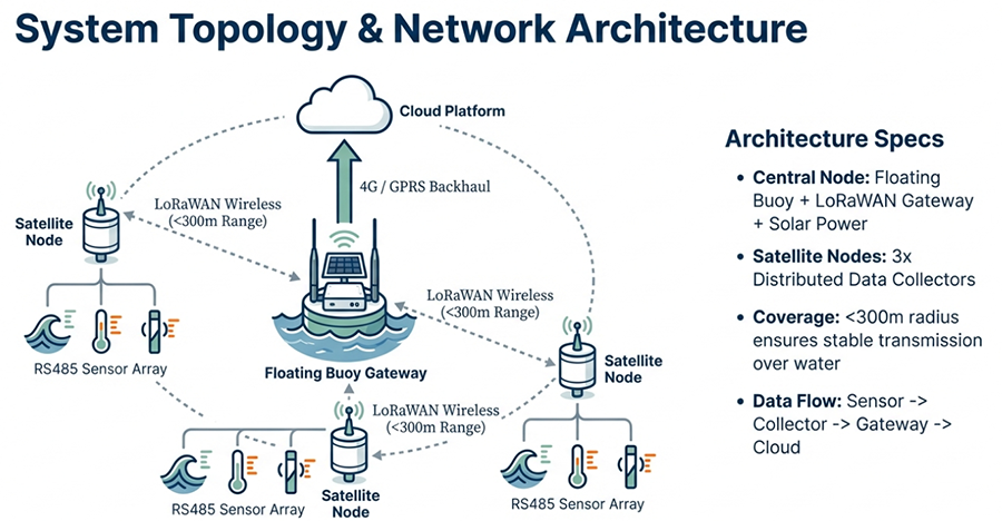
4. Optimizing Aquifer Management via 4G/LoRaWAN Ecosystem

In our field deployments, correlating water quality fluctuations with level changes in real-time allows for predictive aquifer modeling. The system supports multiple wireless backhauls:
• GPRS/4G/WiFi: Best for sites with existing cellular coverage.
• LoRa/LoRaWAN: Ideal for remote marine monitoring or deep-well clusters where a single gateway aggregates data from multiple nodes (up to 300m range per node).
• Cloud Visualization: Our dedicated servers provide real-time dashboards and historical data acquisition, as seen in our marine monitoring node deployments.
water level&ec for deep well

5. Industry-Specific Application Scenarios

Environmental & Municipal
Industrial & Energy
Food & Agriculture
• Sewage Treatment Online Monitoring
• Thermal Power Cooling Water
• High-Density Aquaculture
• Tap Water Quality Distribution
• Metallurgy & Electroplating
• Fermentation Process Control
• Surface Water Salinity Tracking
• Chemical Industry Effluent
• Food Processing & Papermaking
• Textile Printing & Dyeing
• Acid/Alkali Recovery Systems
• Hydroponic Nutrient Leveling

6. Professional Installation: Avoiding the “Dead Cavity” Error

Engineers often overlook the physical dynamics of water flow around the sensor. To maintain E-E-A-T standards in your deployment, follow these protocols:
1. Prevent “Dead Cavities”: In pipeline or submerged installations, ensure the electrode connector is not excessively long relative to the extension. If the probe is tucked too deeply into a narrow fitting, water stays stagnant. This “Dead Cavity” means your sensor is measuring old water, leading to massive data lag and errors.
2. Eliminate Gas Accumulation: For pipeline mounting, ensure the pipe is full. Air bubbles or gas pockets in the measuring chamber will cause disordered, jumping data.
3. Signal Isolation: The measurement signal is a weak electrical signal. The acquisition cable must be independently routed. Never bundle it with high-voltage power lines or control lines; interference can break down the meter’s measurement unit.
4. Electrode Hygiene: Never touch the electrode surface with bare hands. Greasy residues from skin will prevent accurate ions-to-electrode contact, rendering calibration useless.

7. FAQ

Q1: How do I calibrate the sensor if the readings drift?
A: Calibration involves changing the “Electrode Constant” via Modbus. First, set the constant to 1.0 (0×03 E8). Measure a standard solution (e.g., 1413 µS/cm). If the reading is slightly off, adjust the linear multiple (e.g., to 0.98 or 0×03 E6) to match the standard.
Q2: Can the sensor survive high-acid industrial waste? 
A: Yes. The use of a PTFE electrode and a stainless steel pneumatic gauge body ensures resistance to most industrial acids and alkalis. However, avoid mechanical scraping of the electrode during cleaning, as this alters the electrode constant.
Q3: Is the cable length customizable for 50m+ wells? 
A: The cables are specialized, shielded, and factory-fixed. While the standard range is 10m, length must be specified during the order process to ensure correct factory calibration. Replacing cables in the field with non-spec wiring will cause significant measurement errors.
Q4: How do I recover a “lost” device address? 
A: If the Modbus address is forgotten, use the broadcast address 0XFE. Note that the host must be connected to only one slave when using this command to query or reset the original address.
• Request a Custom Quote for Industrial IoT Monitoring Projects

Tags: Deep well water level EC sensor | Water EC & Level sensor with the 4G server and software

For more water sensor information,

please contact Honde Technology Co., LTD.

WhatsApp: +86-15210548582

Email: info@hondetech.com

Company website: www.hondetechco.com


Post time: Jan-27-2026