

Meta Title: Radar Water Level Sensor for Road Underpass Flood Warning
Meta Description: Discover how radar water level monitoring helps detect rising water at road underpasses and low-lying tunnels. Explore Honde’s RD-300S-01 radar sensor, optional electronic water level gauge and wireless flood warning solution.
Primary Keyword: radar water level sensor for flood warning
Secondary Keywords: road underpass flood monitoring, tunnel flood warning system, non-contact radar water level sensor, road flooding detection, electronic water level gauge, smart flood monitoring system, urban flood early warning
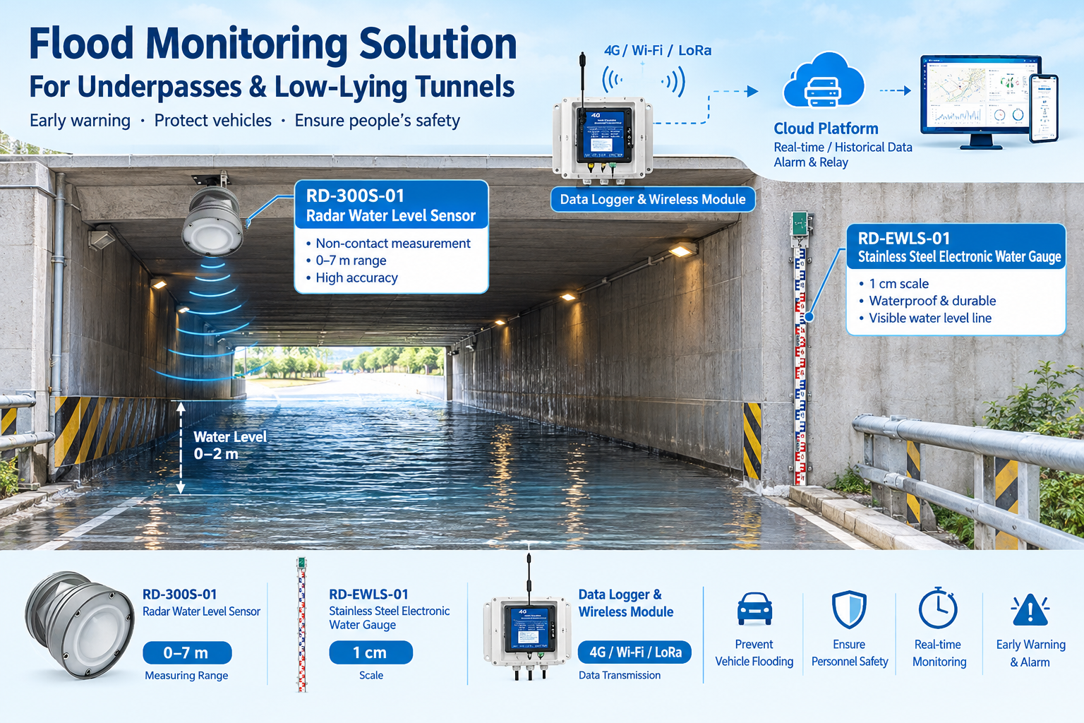
1. Why Road Underpasses Need Real-Time Flood Monitoring
A road underpass can appear completely dry during normal weather and become dangerous within a short period of heavy rainfall. Because the road surface sits below the surrounding ground, rainwater may accumulate faster than the drainage system can remove it.
For drivers, even a relatively shallow layer of water can create a hazardous situation. When water rises rapidly, vehicles may become stranded, traffic can be disrupted and emergency response becomes more difficult.
Japan’s Ministry of Land, Infrastructure, Transport and Tourism has highlighted the risk of flooding at road underpasses when heavy rainfall exceeds the capacity of drainage pumps and channels. Its road-flooding guidance also identifies preventive traffic restrictions and measures to stop vehicles entering flooded areas as important safety measures. Source: MLIT
For municipal road authorities, highway operators and smart-city system integrators, the challenge is to detect rising water early enough to trigger an appropriate response.
A radar water level monitoring system provides a way to measure changing water depth without placing the primary sensor in direct contact with floodwater. When connected to a data acquisition unit, wireless communication system and alarm platform, it can help road management teams monitor vulnerable locations and respond to rising water levels.
Honde Technology Co., Ltd. proposes a solution centered on the RD-300S-01 radar water level sensor, with the RD-EWLS-01 electronic water level gauge available as an optional complementary device.
2. Application Scenario: Flood-Prone Underpasses and Low-Lying Tunnels
The proposed system is designed for locations where water accumulation can develop quickly and where drivers may not immediately recognize the danger.
Typical application areas include:
- Road underpasses beneath bridges and elevated roads.
- Low-lying tunnel entrances and exits.
- Urban road depressions with a history of water accumulation.
- Access roads near drainage channels and pumping facilities.
- Flood-prone road sections monitored by municipal authorities.
During dry weather, the monitoring system establishes the normal road-surface reference. When rainfall causes water to accumulate, the measured distance or water level changes, allowing the system to track the developing situation.
The monitoring objective is not simply to report that water is present. It is to help operators understand how deep the water has become, whether the level is continuing to rise and whether a predefined warning threshold has been reached.
3. Recommended Equipment: RD-300S-01 Radar Water Level Sensor
For overhead monitoring at a road underpass, the proposed primary instrument is the RD-300S-01 radar water level sensor, specified for a 0–7 m measurement range.
Non-contact monitoring from above
The radar sensor can be mounted beneath a suitable bridge ceiling or on an overhead support pole, with the sensing direction aimed toward the road surface.
When the road is dry, the sensor measures the distance to the surface. As water accumulates, the distance to the water surface decreases.
With the mounting height and dry-road reference properly established, the system can calculate water depth from the change in measured distance.
For example, if the reference distance to the dry road surface is 3.00 m and the measured distance to the water surface becomes 2.70 m, the estimated water depth is 0.30 m, assuming the same reference position and a stable installation.
This reference-based method makes it possible to monitor changing road inundation without installing the primary radar sensor directly in the water.
Why radar is suitable for this application
The non-contact design offers several practical advantages:
- No direct immersion: The primary sensing unit can remain above the monitored surface.
- Reduced exposure to muddy water: The sensor does not need to be submerged in sediment-laden floodwater.
- Continuous level tracking: The system can record water-level changes during rainfall events.
- Flexible mounting: Overhead installation can be considered where the structure and measurement geometry permit.
- Remote monitoring potential: A compatible data logger and communication module can transmit readings to a monitoring platform.
Radar measurements still depend on correct installation. The sensor must have a clear measurement path to the water surface, and the selected mounting position should minimize interference from bridge structures, passing vehicles and other reflective objects.
The RD-300S-01′s exact accuracy, beam angle, update interval, environmental rating and output interface should be confirmed against the current product datasheet before final system design.
4. Optional Secondary Device: RD-EWLS-01 Electronic Water Level Gauge
For projects where field personnel need a visible reference at the roadside, the proposed RD-EWLS-01 stainless steel electronic water level gauge can be considered as an additional device.
A visible water-level reference for field personnel
The electronic water level gauge can be installed vertically on a suitable concrete sidewall, subject to the product’s mounting requirements.
Its marked scale provides a direct visual reference for personnel inspecting the site. According to the supplied application specification, the scale uses 1 cm graduations.
The device can complement remote electronic monitoring by helping road maintenance staff and emergency personnel visually assess the water level at the location.
Its role differs from that of the overhead radar sensor:
- The radar sensor provides non-contact measurements from above.
- The electronic water level gauge provides a visible reference at the wall.
- Together, they can support remote monitoring and on-site assessment.
The electronic gauge should not be treated as a substitute for an engineered warning system. Any electrical, communication or visual indication functions should be confirmed against the selected product configuration.
5. One Sensor or Two? Choosing the Right Configuration
Not every flood-prone location requires the same monitoring arrangement. The choice depends on site risk, installation conditions, the need for visual inspection and the required level of redundancy.
| Configuration | Equipment | Suitable application |
|---|---|---|
| Basic monitoring | RD-300S-01 radar water level sensor | Single-point monitoring of a vulnerable underpass |
| Monitoring with visual reference | RD-300S-01 + RD-EWLS-01 | Sites where both remote measurements and on-site water-level indication are useful |
| Enhanced monitoring and redundancy | Radar sensor plus a separately designed secondary measurement or detection channel | Higher-risk locations where independent fault detection or backup measurement is required |
For a typical installation, the RD-300S-01 can serve as the primary measurement device. The RD-EWLS-01 can be added where its visual scale provides practical value.
If a project requires true redundancy, the engineering team should determine whether the secondary device supplies an independent measurement, how discrepancies will be detected and what action the system should take if one device fails. Two instruments installed at the same location do not automatically provide complete redundancy.
6. How the Road Flood Warning System Works
The proposed solution connects water-level measurement with data acquisition, wireless communication and alarm handling.
Step 1: Measure the road water level
The RD-300S-01 is installed above the road surface and configured using the correct reference distance.
The system tracks the distance to the reflecting surface and converts the measurement into water depth when the reference conditions are correctly established.
Step 2: Transmit the monitoring data
A compatible handheld meter, data logger or controller collects the sensor readings.
Depending on the selected hardware, communication options may include GPRS, 4G, Wi-Fi, LoRa or LoRaWAN. MQTT/JSON transmission can be used where supported by the device and receiving platform.
Step 3: Compare readings with warning thresholds
The controller or monitoring software compares the measured water depth with predefined warning levels.
For example, a project might define separate thresholds for an initial warning, a high-water alarm and a road-closure response. The actual values must be determined by the responsible road authority according to road geometry, vehicle clearance, drainage behavior and local safety procedures.
Step 4: Notify the responsible team
A compatible cloud platform can display real-time readings and historical trends. Configured alarm functions can notify responsible personnel when the water level reaches a specified threshold.
Where required, a suitable relay output or control interface can be integrated with warning lights, roadside message signs, barriers or a traffic management system.
Step 5: Support a coordinated safety response
The responsible authority can use the monitoring information as one input when deciding whether to inspect the site, activate a warning sign or restrict vehicle access.
The system’s purpose is to provide timely measurement and alarm information. Safe road closure and emergency response still depend on the project’s complete control design, communication reliability and operating procedures.
7. Honde Smart Flood Monitoring Solution
Honde’s proposed solution can be arranged into four functional layers.
| System component | Function |
|---|---|
| RD-300S-01 radar water level sensor | Measures the distance to the water surface for water-depth calculation |
| RD-EWLS-01 electronic water level gauge, optional | Provides a visible water-level reference |
| Handheld meter or data logger with screen | Supports local readings and data collection, subject to compatibility |
| Wireless communication module | Transmits data using the selected supported communication method |
| Cloud server and monitoring software | Displays current readings and historical records |
| Alarm relay and external warning equipment | Supports configured alarm outputs and compatible external integration |
The typical data flow is:
Radar Water Level Sensor → Data Logger/Controller → Wireless Communication → Cloud Platform → Alarm Notification → Road Safety Response
For a multi-site deployment, the monitoring platform can be designed to bring readings from multiple underpasses into a centralized interface. This can help road management teams review conditions across different locations without relying entirely on manual site inspections.
The exact communication distance, power supply, solar power requirements, data reporting interval and platform integration should be confirmed during project planning.
8. Installation Considerations for Reliable Flood Monitoring
A radar-based system is only useful when the installation produces measurements that accurately represent the water depth at the monitored road section.
Establish the correct dry-road reference
Before commissioning, record the distance between the radar sensor and the relevant road-surface reference. Configure the water-depth calculation using this value.
If the sensor mounting height changes or the road surface is altered, the reference should be checked again.
Choose a clear measurement path
Install the sensor where its measurement beam can reach the monitored surface without obstruction. Bridge beams, signs, cable trays and other structures can create unwanted reflections.
The measurement location should also be selected with consideration for the vehicle path and expected water accumulation pattern.
Consider vehicle movement and splashing
Passing vehicles can create temporary reflections or splashes. Suitable mounting geometry, measurement filtering and alarm delay logic can help reduce nuisance alarms.
The configuration should be tested under actual site conditions rather than assuming every instantaneous reading represents a sustained change in water depth.
Confirm the 0–7 m measurement range is suitable
The specified range of the RD-300S-01 should be checked against the actual mounting height and maximum expected water depth.
The usable measuring range must accommodate the dry-road reference distance, anticipated inundation depth and required installation clearance.
Define warning thresholds before deployment
Warning thresholds should reflect the site’s risk assessment and response plan. A low threshold may be used for early notification, while higher thresholds may trigger more urgent action.
The road authority should also define who receives each alarm, how quickly it must be acknowledged and what action follows a sensor or communication failure.
Test the full alarm chain
Commissioning should verify the complete process from measurement to action:
- Confirm the radar reading under dry conditions.
- Verify the water-depth calculation using a known reference.
- Check data transmission and cloud display.
- Test the configured alarm thresholds.
- Verify relay outputs and connected warning equipment, where installed.
- Test communication-loss and sensor-fault handling.
For high-risk underpasses, monitoring should complement appropriate drainage maintenance, physical warning devices and a defined traffic restriction procedure.
9. Frequently Asked Questions
Can a radar water level sensor measure road flooding without touching the water?
Yes. A suitable radar sensor measures the distance to the reflecting water surface from an overhead installation. Water depth can then be calculated from the change relative to the established dry-road reference.
Why choose radar instead of a submerged water level sensor?
Radar avoids placing the primary sensor directly in floodwater, which can be advantageous at sites with muddy water, floating debris or difficult access. However, the choice should consider mounting conditions, required accuracy, measurement range and the site’s specific hazards.
Is the RD-300S-01 suitable for a road underpass?
The proposed application uses the RD-300S-01, specified with a 0–7 m range, as an overhead radar water level sensor. Suitability for a particular underpass depends on mounting height, target geometry, sensor specifications and the maximum expected water depth.
Why add an electronic water level gauge?
The RD-EWLS-01 can provide a visible scale for personnel at the site. It complements remote electronic monitoring by offering a direct visual reference, subject to the selected model’s installation and operating requirements.
Can the system automatically close a road?
The monitoring system can support road-closure decisions and may be integrated with compatible barriers, warning lights or traffic signs. Automatic closure requires additional control hardware, approved response logic and coordination with the responsible road authority.
Can water levels from several underpasses be monitored centrally?
Yes, a suitable cloud platform can be configured to receive readings from multiple monitoring points when the sensors, communication equipment and software interfaces are compatible. The final design should account for network coverage, power availability and communication failure handling.
10. Request a Flood Monitoring Configuration for Your Project
At flood-prone road underpasses, the difference between a dry road and a dangerous water depth can develop quickly during heavy rainfall. Reliable water-level measurement helps road management teams understand changing conditions and make better-informed safety decisions.
The Honde RD-300S-01 radar water level sensor provides a proposed non-contact measurement option for underpasses, low-lying tunnels and other vulnerable road locations. The RD-EWLS-01 electronic water level gauge can be added where a visible water-level reference is also required.
With compatible data acquisition, wireless communication, cloud monitoring and alarm integration, the solution can form part of a wider smart-city flood monitoring system.
Contact Honde Technology Co., Ltd.
- Website: https://www.hondetechco.com/
- Email: info@hondetech.com
- WhatsApp: +86-15210548582
Contact our team to discuss your road underpass flood monitoring project, installation height, required measuring range, communication method and alarm integration requirements.
For a project quotation, please provide the installation location, mounting height, maximum expected water depth, preferred communication method and whether road signs or barriers need to be integrated.
Post time: Oct-20-2026