
Why Conventional Anemometers Fail in Industrial Confinement
Drawing from over 15 years of experience in manufacturing industrial instrumentation, we have observed that standard, fixed-position sensors are often the primary cause of data inaccuracies in duct monitoring and machinery ventilation. The core issue is airflow directionality. In narrow spaces—such as HVAC ducts, cooling bays, or complex machinery internals—airflow is rarely uniform.
Traditional rigid sensors often suffer from sensor installation constraints, where the probe cannot be positioned to face the wind vector directly. If an impeller is even slightly misaligned with the flow, the measured velocity drops significantly. Furthermore, the “low-start wind speed” requirements of industrial fans require a sensor that can be positioned precisely in the center of the flow path. A sensor that lacks physical flexibility is effectively obsolete in high-precision B2B environments.
Key Technical Specifications
For system engineers and procurement officers, the following technical data defines the performance envelope of the RD-IWSS-02 adjustable impeller sensor.
| Parameter | Technical Specification |
| Brand | Honde Technology |
| Wind Speed Range | 0 ~ 30m/s |
| Accuracy | ±3% |
| Induction Principle | High-Precision Impeller Sensing Core |
| Output Interfaces | RS485 (Modbus-RTU), 4-20mA, DC0-10V, DC0-5V |
| Power Supply | DC12 ~ 24V 1A |
| Operating Temperature | -30 ~ 80℃ |
| Working Humidity | 5%RH ~ 90%RH |
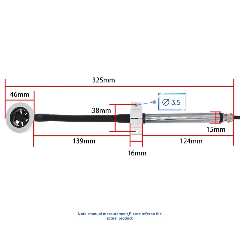
| Head Diameter | 46mm |
| Total Length | 325mm (Integrated flexible neck) |
Anatomy of an Adjustable Impeller Sensor
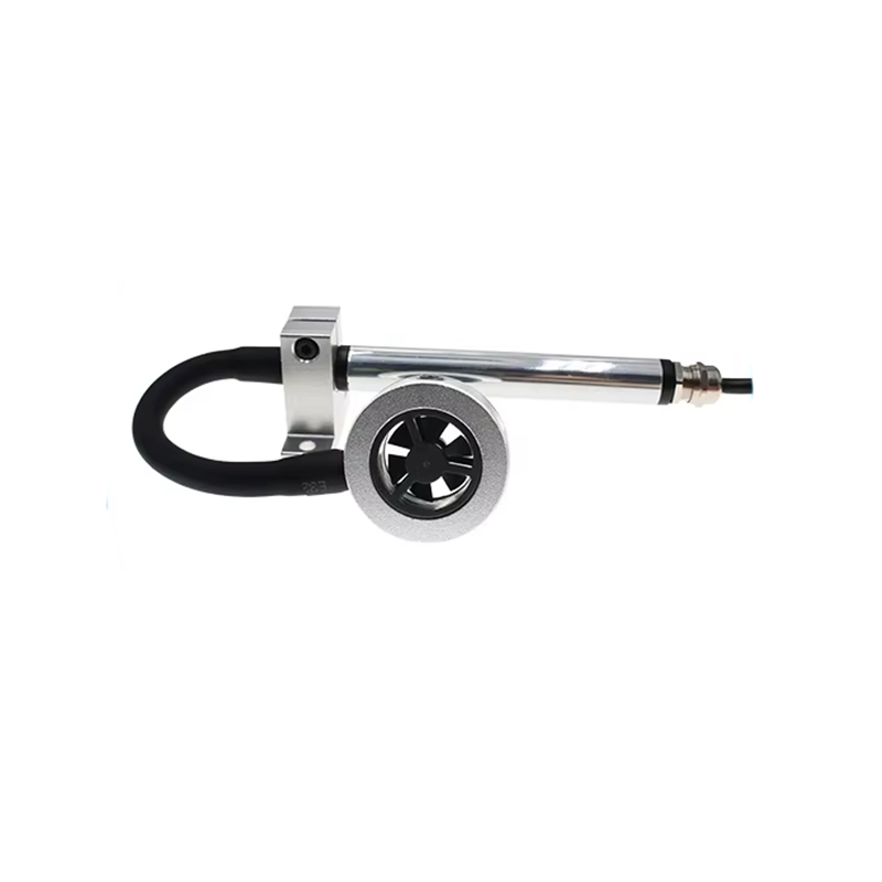
The RD-IWSS-02 is engineered to bridge the gap between high-precision sensing and difficult physical environments.
- Flexible Directional Neck: The 46mm impeller head is connected to the mounting base via a heavy-duty flexible neck. This allows for 360-degree orientation adjustments, ensuring the impeller faces the wind source directly even when the mounting bracket is offset.
- Optimized Reach: With a total length of 325mm—consisting of a 139mm front segment and a 124mm rear segment separated by a 16mm mounting bracket—the sensor provides the necessary depth to reach into deep ducts or through thick insulation.
- High-Stability Sensing Core: Unlike thermal film sensors which can be sensitive to ambient temperature fluctuations, the mechanical impeller core offers superior long-term stability and resistance to dust accumulation in industrial environments.
For automation engineers, the RD-IWSS-02′s implementation of the Modbus-RTU protocol allows for high-density sensor networking.
Technical Data Parsing
To query the wind speed, the host computer sends an inquiry frame. For a device at address 01:
- Inquiry Frame:
01 03 00 00 00 01 84 0A - Response Frame:
01 03 02 02 18 B9 2E
02 18 is in hexadecimal. When converted to decimal, it equals 536. Based on the device’s magnification factor of 100, the calculation is: 536 / 100 = 5.36 m/sSystem Flexibility
- Baud Rate Configuration: The default is 9600 bps, but it can be modified (Register
00 67) to values ranging from 2400 to 115200 bps to accommodate complex bus lengths. - Universal Addressing: If a device’s address is lost, the universal address
FA(250) can be used to query and reset the hardware ID.
Industry Applications: Where This Sensor Excels
The RD-IWSS-02′s adaptability makes it a primary choice for several specialized sectors:
Meteorology & Environment
- Micro-Climate Monitoring: Measuring air exchange rates in restricted environmental chambers or ventilation shafts.
- Meteorological Stations: Serving as a secondary sensor in areas where standard wind vanes cannot fit.
Agricultural Automation
- Silo & Greenhouse Ventilation: Ensuring consistent airflow around sensitive crops and stored grains where space is at a premium.
- Automated Livestock Farming: Monitoring localized air velocity in narrow animal housing bays.
Infrastructure & Heavy Industry
- Power Plants & Railways: Monitoring cooling air flow in narrow electrical cabinets and transformer rooms.
- Construction & Medical: Measuring airflow in cleanrooms and HVAC ducts where precise duct-center placement is required for regulatory compliance.
Implementation Guide & Engineering Insights
Analog Signal Calibration
When utilizing 4-20mA or 0-10V outputs, engineers should use the standard linear conversion formula to translate analog signals into physical values:
Where:
- A2 / A1: Wind speed range limits (30 and 0).
- B2 / B1: Analog output limits (e.g., 20mA and 4mA).
- X: The raw current or voltage value measured by the PLC.
- C: The calculated wind speed in m/s.
Conclusion and Call to Action
As industrial systems move toward more granular monitoring in 2026, the ability to measure wind speed in confined spaces is no longer a luxury but a requirement for efficiency. The Adjustable Angle Impeller Wind Speed Sensor (RD-IWSS-02) provides the physical flexibility and digital precision required for modern PLC and DCS environments.
Optimize your industrial airflow monitoring today:
- Download the full RD-IWSS-02 Technical Manual
- Request a custom quote for your specific project requirements
Contact Information:
- Company: Honde Technology Co., Ltd.
- Website: www.hondetechco.com
- Email: info@hondetech.com
Post time: Apr-24-2026